You can add gerber layers to your imported CAD or X-Y Rotation (XYR) data. The gerber layer(s) can add more information to the display. For example the gerber silk screen layer can add component polarities, package outlines, board outline and additional reference designator detail.
Also fiducial marks and other needed data maybe in the gerber files and may need to be imported to be used.
Before Gerber silkscreen added:
After Gerber silkscreen added:
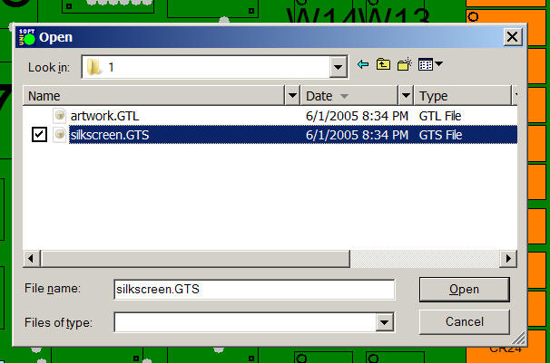
To use: First import your CAD or XYR data. Next select ADD LAYER from the GERBER-CONNECTION menu and select the gerber layer to be imported and click OPEN.
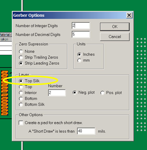
Next select either TOP SILK or BOTTOM SILK and click OK. Note as needed you can also select either TOP, INTERIOR or BOTTOM.
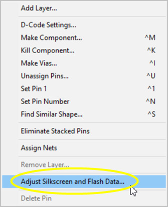
In some cases the gerber data may not be in alignment with the CAD data and in these cases the gerber data needs to be adjusted so it lines up with the CAD data. To do this click ADJUST SILKSCREEN AND FLASH DATA.
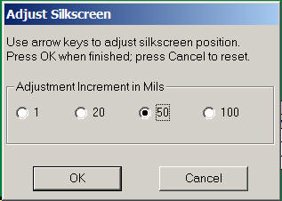
The following screen appears for adjustment. Select the movement increment desired in the ADJUSTMENT INCREMENT IN MILS field. Use the up and down arrow keys to adjust to the new position needed for the gerber data layer. When the position desired is achieved click OK. Repeat if necessary.
At this point the gerber layer you imported is displayed along with the CAD or XYR data and they should be in alignment.