When designing a PCB CAD systems standardly lay out the components on the top and the bottom of the PCB relative to the top side of the PCB. Also the top side components are normally rotated in the counter clockwise (CCW) direction when viewed from the top of the PCB. So since the bottom side rotations are relative (tied to) the top then the bottom side component rotations are rotated clockwise (CW) when the PCB is viewed from the bottom.
Although there has been progress in recent years there really has not been a global standard for zero degrees rotation of components. Possibly the most agreed upon rotation standard is the IPC7351B Level A and this is the standard that Unisoft uses for 0 degrees rotation of components to help solve this rotation inconsistency problem.
So if a CAD file is imported into the Unisoft software and it does not explicitly define the rotation of a components then Unisoft will set the rotation to the IPC7351B Level A standard automatically.
However if the CAD file data explicitly defines the rotations of the components then on importing of the CAD file those rotations are used. If desired the Reset Rotation feature can be used to override these rotations and set them back to the standard.
The Reset Rotation feature of the Unisoft software will reset components back to the IPC7351B Level A zero degrees standard and many customers find this feature useful to normalize their component rotations. This is especially true if they are electronic contract manufacturers and deal with many different customers CAD files which sometimes exhibit different rotations for the same component package orientation.
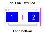
The following rotations are normally correct for 2 pin component packages per the IPC-7351B Level A zero degrees orientation standard:
| Degrees of rotation for component package per IPC-7351B Level A zero degrees orientation standard | Top side rotations indicated on the Unisoft software display for 2 pin components viewed from the top side | Bottom side rotations indicated on the Unisoft software display for 2 pin components viewed from the bottom side |
|---|---|---|
| 0 | 0 - (0 clicks of 90 CCW) - example pin 1 to left of 2 | 0 - (0 clicks of 90 CW) or (0 clicks of 90 CCW) - example above pin 1 to left of 2 |
| 45 | 45 - (0.5 clicks of 90 CCW) | 315 - (3.5 clicks of 90 CW) or (0.5 clicks of 90 CCW) |
| 90 | 90 - (1.0 click of 90 CCW) - example pin 1 below pin 2 | 270 - (3.0 clicks of 90 CW) or (1.0 click of 90 CCW) - example above pin 1 below pin 2 |
| 135 | 135 - (1.5 clicks of 90 CCW) | 225 - (2.5 clicks of 90 CW) or (1.5 clicks of 90 CCW) |
| 180 | 180 - (2.0 clicks of 90 CCW) - example pin 1 to right of 2 pin | 180 - (2.0 clicks of 90 CW) or (2.0 clicks of 90 CCW) - example above pin 1 to right of 2 pin |
| 225 | 225 - (2.5 clicks of 90 CCW) | 135 - (1.5 clicks of 90 CW) or (2.5 clicks of 90 CCW) |
| 270 | 270 - (3.0 clicks of 90 CCW) - example pin 1 above pin 2 | 90 - (3.0 click of 90 CW) or (1.0 clicks of 90 CCW) - example above pin 1 over pin 2 |
| 315 | 315 - (3.5 clicks of 90 CCW) | 45 - (0.5 clicks of 90 CW) or (3.5 clicks of 90 CCW) |
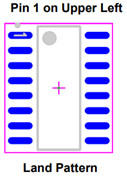
The following rotations are normally correct for 3 pin and greater component packages (IC's, etc.) per the IPC-7351B Level A zero degrees orientation standard:
| Degrees of rotation for component package per IPC- 7351B Level A zero degrees orientation standard | Top side rotations indicated on the Unisoft software display for 3 pins or greater components viewed from the top side | Bottom side rotations indicated on the Unisoft software display for 3 pins or greater components viewed from the bottom side |
|---|---|---|
| 0 | 0 - (0 clicks of 90 CCW) | 0 - (0 clicks of 90 CW) or (0 clicks of 90 CCW) - example above pin 1 upper left |
| 90 | 90 - (1.0 click of 90 CCW) | 270 - (3.0 clicks of 90 CW) or (1.0 click of 90 CCW) - example above pin 1 upper left |
| 180 | 180 - (2.0 clicks of 90 CCW) | 180 - (2.0 clicks of 90 CW) or (2.0 clicks of 90 CCW) - example above pin 1 lower right |
| 270 | 270 - (3.0 clicks of 90 CCW) | 90 - (1.0 click of 90 CW) or (3.0 clicks of 90 CCW) - example above pin 1 upper right |
As can be seen above topside rotations are straight forward but the bottom side rotations are less so.
The PCB manufacturing production equipment that needs this rotation information, such as Pick & Place assembly or AOI equipment, may differ on what rotations it expects between vendors and models and normally the Unisoft software will take care of any corrections.
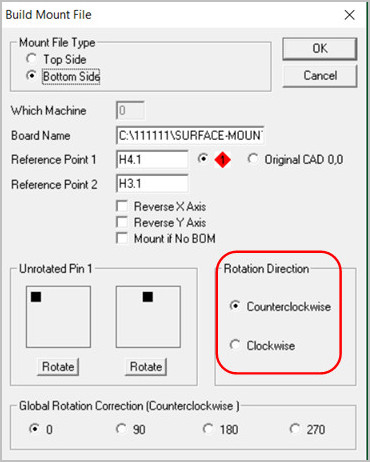
If modifying the rotation is desired controlling the rotation can be done in a number of ways within the Unisoft software. Besides the Reset Rotation feature explained above, for example, in the window below, although it is normally not the standard, the CCW rotation can be adjusted to CW. For details on rotation modification options go to Rotations - Rotation modification options.
Rotations - Component zero orientation info IPC-7351
Rotations - Rotation modification options