Skip navigation
For over 35 years, Intelligent PCB Manufacturing
Automation Software
Be production ready in minutes, not days.
Creating assembly process documents is straightforward using the Unisoft software. Component part numbers can be broken out into steps and unique colors can be assigned. Then assembly process documents and kitting labels similar to the two figures below are created.
Below we will take you through a simple sample of how this process is done.

There are basically 4 steps to creating assembly documents:
For our sample PCB below first we will divide the board assembly into 4 Steps. Second unique colors will be assigned to the component part numbers in each step. Next annotation overlays will be added to the steps. Then the assembly documents will be printed.
Note: The procedure below is a brief overview of the process of assembly document creation. Contact Unisoft for more details or go to the Quick Start manual and go to section "Tutorial 1 — Creating assembly/process sheets, annotation overlays and kitting labels".
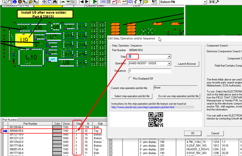
Step 1. For our PCB in the figure below Step 1 is assigned to the first Part Number and Step 2 to the second part number and Step 3 to the other Part Numbers. Note: When a PCB is first imported into the Unisoft software all part numbers are assigned to Step 1.
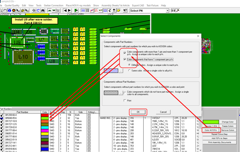
Step 2. At this point either automatically or manually assign colors. For example in the figure below the colors are assign automatically so it assigned red to Step 1, green to Step 2 and so on.
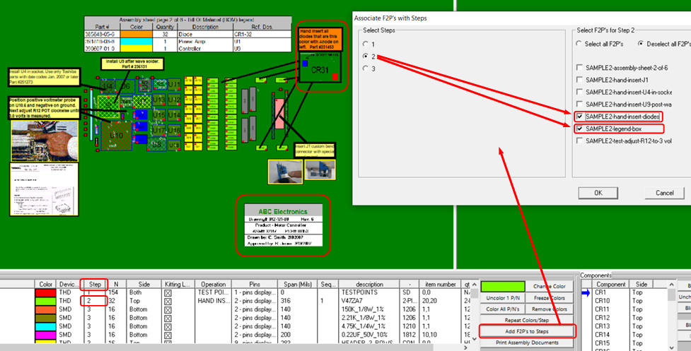
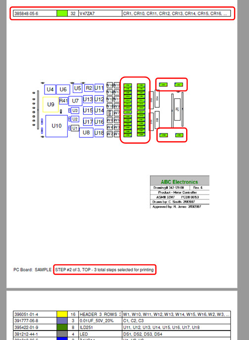
Step 3. Optionally add annotation overlays to Steps. For example in the figure below for Step number 2 the annotation overlays named SAMPLE2-hand-insert-diodes and SAMPLE2-legend-box that are outline in red on the display are assigned to Step number 2. So when Step 2 is printed only these 2 annotation overlays will appear on that step.
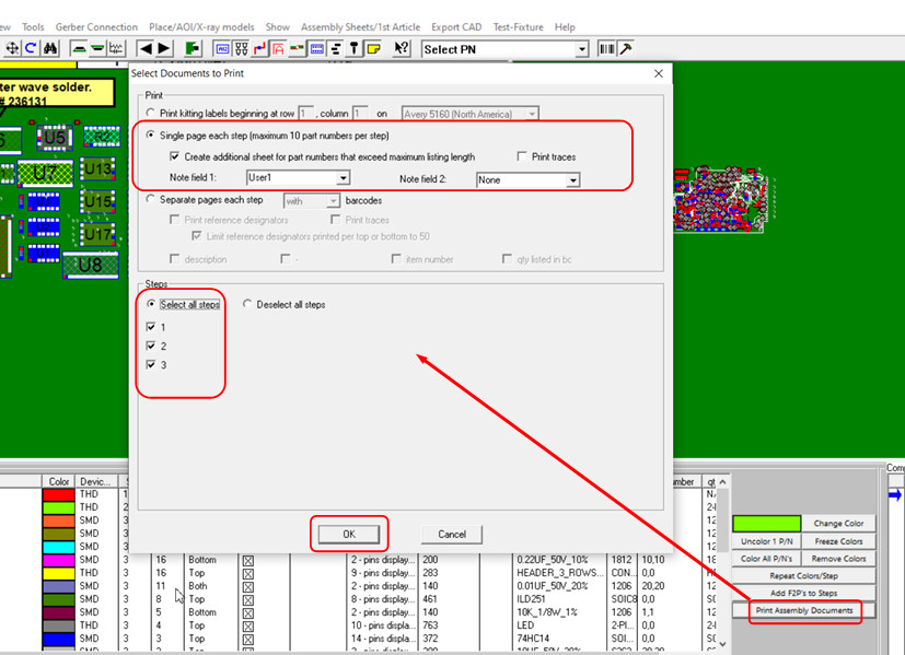
Step 4. Print out the assembly documents. In the figure below all steps have been selected and the "Single page each step" format option has been selected.
The assembly document created contains all 3 Steps. As can be seen in the figure below for Step 2 in the printout the part number was assigned the color green and all the components with that part number are colored green.
Contact Unisoft for more details or go to the Quick Start manual and go to section "Tutorial 1 — Creating assembly/process sheets, annotation overlays and kitting labels".